Amek Power Supply repair?

Nice work. You've certainly got to share a pic or two of the end result when done with it. :yesway:

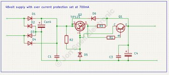
1783974842428.png

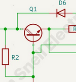
A rare dual collector transistor? ;)

Another method I use besides the "image way" is to put a light on the bench and shine through the PCB from underneath. This works great with most dual layer boards.
 
Nice work. You've certainly got to share a pic or two of the end result when done with it. :yesway:
View attachment 111930

A rare dual collector transistor? ;)

Another method I use besides the "image way" is to put a light on the bench and shine through the PCB from underneath. This works great with most dual layer boards.
That is a good idea but to save effort, photograph the topside and invert it on your computer. Use Preview on a MAC and the menu allows for easy editing. Don't have to take the board with you to the desk that way.

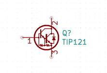
Transistor shown;
Tip121 Darlington.
It is the symbol for a Darlington transistor. They used to be drawn as two transistors in the same can, which is what they are in reality. Progress and standardisation, (maybe to save on printing ink ):ROFLMAO:
 
That is a good idea but to save effort, photograph the topside and invert it on your computer. Use Preview on a MAC and the menu allows for easy editing. Don't have to take the board with you to the desk that way.

Sure, though for relatively simple circuits I tend to sketch them out by hand as I trace them using the light underneath to follow the traces without flipping the board all the time. When I have the pencil sketch, I'll recreate it nicely in KiCAD.

Transistor shown;
Tip121 Darlington.
It is the symbol for a Darlington transistor.

Yes, I see that; it's just the standard NPN transistor symbol. If you look closely at your screenshot or the section I highlighted, it seems there are two symbols overlaid. There appears to be what looks like a second collector, you can see the dangling line ends. Not that it matters, the schematic is clear, of course. :)

I just checked in KiCAD and my version is a bit older, but a TIP121 still shows as a real darlington transistor:

1784011718689.png

I hope they haven't changed that, would be a little confusing.
 
Sure, though for relatively simple circuits I tend to sketch them out by hand as I trace them using the light underneath to follow the traces without flipping the board all the time. When I have the pencil sketch, I'll recreate it nicely in KiCAD.


Yes, I see that; it's just the standard NPN transistor symbol. If you look closely at your screenshot or the section I highlighted, it seems there are two symbols overlaid. There appears to be what looks like a second collector, you can see the dangling line ends. Not that it matters, the schematic is clear, of course. :)

I just checked in KiCAD and my version is a bit older, but a TIP121 still shows as a real darlington transistor:

View attachment 111935

I hope they haven't changed that, would be a little confusing.
Of course, why didn't I see that!
Revised schematic attached.
 

Attachments

Interestingly enough, D5 is a 1n4003, not a zener, so Q2 is just a switch with a slow start.
Q1 and R3 check for short circuits. The actual DC volts is 51 volts, so no drama there.

I think I will use standard regulators 7818 and 7918 for the supply to a pair of 2n3055 and MJ2955 transistors, to keep the power output similar but a better regulation.
The boards have been butchered so badly in the past, not a lot else I can do about them. They are hidden inside the rear cover, so not on show.

Edit; More info added.
 
I think I will use standard regulators 7818 and 7918 for the supply to a pair of 2n3055 and MJ2955 transistors, to keep the power output similar but a better regulation.

That should do the trick indeed. Assuming the current draw is fairly low as expected, you probably won't need much in the way of heatsinks, either.
 
That should do the trick indeed. Assuming the current draw is fairly low as expected, you probably won't need much in the way of heatsinks, either.
The specification for the + - 18v rails are 8 Amps, so a pair of 2n3772, driven by a 7818 will suffice, and the opposite polarity for the other side.
The 5 volt supply is 5 Amps so a single 2n3771 will do.
I think it was overengineered, as I have never seen an analogue desk draw that much current!
I have prepared the boards, ready to build on Thursday as she who must be obeyed has told me, "We are going out on Wednesday".

So that's that then.

I listen and play songs like this,
Makes life more bearable :pound-hand:
 
Last edited:
I think it was overengineered, as I have never seen an analogue desk draw that much current!

It would have to be awfully large and have some auxiliary functions to warrant that draw indeed. Probably overspec'd which is not a bad thing, agree.

I listen and play songs like this,

I can't really stomach the AI stuff. The idea is funny enough and even the lyrics would be passable as a pub song but it's just too 'canned' for me. Certainly understand the gist. My better half also has the uncanny knack to wait until the least inopportune moment to declare that "we" need to do something... such is life.
 
It would have to be awfully large and have some auxiliary functions to warrant that draw indeed. Probably overspec'd which is not a bad thing, agree.


I can't really stomach the AI stuff. The idea is funny enough and even the lyrics would be passable as a pub song but it's just too 'canned' for me. Certainly understand the gist. My better half also has the uncanny knack to wait until the least inopportune moment to declare that "we" need to do something... such is life.
It wasn't me, Phew!
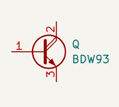
The original Darlington was a BDW93.
When we enter BDW93 into Kicad 10.02 this is what we get;
The same on ver 9.0 Odd isn't it. I was doubting my sanity for a moment :ROFLMAO:
 

Attachments

When we enter BDW93 into Kicad 10.02 this is what we get;
The same on ver 9.0 Odd isn't it. I was doubting my sanity for a moment :ROFLMAO:

Ha, yes - same in my older version. I'm fairly sure I've actually seen this on a schematic before, though I don't recall when/what of. Strange, though, to add that extra collector as there's no additional 'connection point' in the symbol. Not quite sure what the reasoning (if any) is behind that one. The 'comprehensive' symbol for the TIP121 makes sense, but this ... beats me.

Ah well, learned something, I guess. Thanks. :)
 
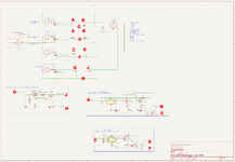
The complete power supply design keeping original boards, (even though they are mutilated beyond retrieval).
The front panel lights will be next.
Photos of the completed power supply will follow when I am happy with it. The power supply will be returned to its owner with age related marks on it but fully functional.
Schematic attached.
 

Attachments

Very nice indeed, good work. I was looking at the overvoltage protection when it dawned on me that the current rating of the fuses by far exceeds the current rating of the DIN 6 connector, hehe. Is it a large desk? I could envision very high but brief inrush current. :shrug:
 
Back
Top