OP
ivan H
Ambassador of Tubes & Grooves
Thanks for the kind words guys. Being here with all the fine folk at TTR is an honorable & a privilege.@ivan H
Watching you work is an honor and a privlege.
Sysco, yes, the heater CT is grounded along with the inputs & V1 cathodes, hopefully you can see it here

I'll try to elaborate on why to do this. You want to ground the heater supply in the "quietest" point, so as far from the PT (which is a large hum source) as possible. Electrically (& in a perfect world, where both sides of the heater winding are "balanced"), you could think of the heater CT as a pivot point, about which the opposing voltage in each half of the heater winding swings. So no current should flow in the CT. As there no such thing as a perfect world, or perfectly balanced heater winding, a little current does flow in the CT. As such, grounding it at the quietest ground is advantageous. The same applies to heater supply's using an "artificial" CT (two 100 ohm resistors). You want to ground the resistors as far from the PT as possible, so usually at V1.
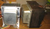
I never use PT mounting bolts as ground points, they pass through the PT laminate & a transformer works off (fluctuating) magnetics, so using as a ground tie point will introduce hum. Cheers
Edit: re heater CT grounding. Even with a "perfectly balanced" winding, you want the CT grounded at the quietest point as any noise (hum) will be injected into (or superimposed on) the supply through the CT (pivot point). That some current flows in the CT is even more reason to ground it away from the PT. Cheers
Last edited: