
You are using an out of date browser. It may not display this or other websites correctly.
You should upgrade or use an alternative browser.
You should upgrade or use an alternative browser.
Watkins Warrior repair
- Thread starter Jon Snell
- Start date


OP

Jon Snell
Active Member

The Watkins Dominator was a nice amplifier, they made three models, similar power as the AC15 as I recall. You have good taste sir.
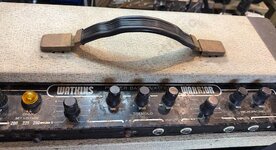
This amplifier lived for years in a damp garden shed/studio, and there is a lot of rust on the faceplate. Luckily the chassis was stove enamelled when it was made and survived intact and almost damage free.
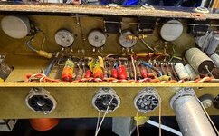
The valve sockets are plated nickel brass, with no signs of damage as all the valves were present when stored, but removed, for other projects I presume, leaving superficial watermarks, that should wipe off with a cotton bud and IPA fingers crossed. If not I will replace any damaged ones.
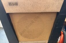
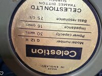
I photographed the loudspeaker purposely like the picture as it was fitted upside down
It is on the bench now and assuming I have all that I need in stock, and not too much repair work on, will be completed in a week or so.
There is no service information available from the usual sources, so it may take a little time to work out what that pre-set does, as there is no way of knowing without it powered up and working.
Tremolo balance I would imagine, as it is added on with a piece of Veroboard.
More to follow as I progress.
Edit; More infor added.
This amplifier lived for years in a damp garden shed/studio, and there is a lot of rust on the faceplate. Luckily the chassis was stove enamelled when it was made and survived intact and almost damage free.
The valve sockets are plated nickel brass, with no signs of damage as all the valves were present when stored, but removed, for other projects I presume, leaving superficial watermarks, that should wipe off with a cotton bud and IPA fingers crossed. If not I will replace any damaged ones.
I photographed the loudspeaker purposely like the picture as it was fitted upside down
It is on the bench now and assuming I have all that I need in stock, and not too much repair work on, will be completed in a week or so.
There is no service information available from the usual sources, so it may take a little time to work out what that pre-set does, as there is no way of knowing without it powered up and working.
Tremolo balance I would imagine, as it is added on with a piece of Veroboard.
More to follow as I progress.
Edit; More infor added.
Attachments
Last edited:
OP
Jon Snell
Active Member
Spent a couple of hours on it this morning.
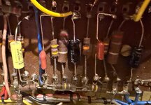
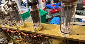
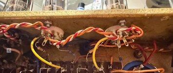
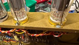
Four B9A sockets are fine, but the EL84 sockets are junk. Replaced the sockets, G1, G2 resistors and fitted new yellow cathode feed wires.
Powered it up for the first time as it now has new smoothing and coupling capacitors that showed leaky or high ESR with new valves.
Cleaned up the pots with contact cleaner with lubricant. https://uk.rs-online.com/web/p/electronics-cleaners/1014937?gb=a https://uk.rs-online.com/web/p/electronics-cleaners/1316178
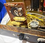
The little Veroboard pot is no longer a mystery. The slide switch selects pre-set gain or full gain. Not sure what the slide switch used to do though.
The tremolo is next to sort out, should be easy, phase shift sine wave oscillator, speed and level controls. It uses the first two input sockets only. I did notice the rusty RCA socket and the last techie shorted it out underneath ... we'll see how it goes.
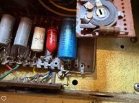
Here are some more inner pictures of the way it is progressing;
Four B9A sockets are fine, but the EL84 sockets are junk. Replaced the sockets, G1, G2 resistors and fitted new yellow cathode feed wires.
Powered it up for the first time as it now has new smoothing and coupling capacitors that showed leaky or high ESR with new valves.
Cleaned up the pots with contact cleaner with lubricant. https://uk.rs-online.com/web/p/electronics-cleaners/1014937?gb=a https://uk.rs-online.com/web/p/electronics-cleaners/1316178
The little Veroboard pot is no longer a mystery. The slide switch selects pre-set gain or full gain. Not sure what the slide switch used to do though.
The tremolo is next to sort out, should be easy, phase shift sine wave oscillator, speed and level controls. It uses the first two input sockets only. I did notice the rusty RCA socket and the last techie shorted it out underneath ... we'll see how it goes.
Here are some more inner pictures of the way it is progressing;
Attachments

PelliX
Well-Known Member
...and you used bolts instead of rivets. Good man.Four B9A sockets are fine, but the EL84 sockets are junk. Replaced the sockets,

OP
Jon Snell
Active Member
The reason I use nuts and screws is that I may well be the next person to fix it and I don't like nasty time-consuming extras to have to drill out or work around.
If the manufacturers realised that nuts and bolts are workable, but rivets are not. Life would be much easier for the engineer who has to fault find and work on their gear, leaving a tidy as well as a functional job.
If the manufacturers realised that nuts and bolts are workable, but rivets are not. Life would be much easier for the engineer who has to fault find and work on their gear, leaving a tidy as well as a functional job.
OP
Jon Snell
Active Member
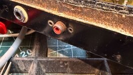
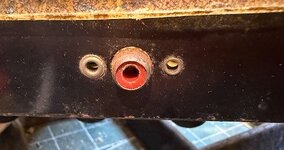
The tremolo circuit requires a short circuit on the RCA connector to work.
This will be removed and replaced with a quality connector. I will then make a foot switch with latching contacts.
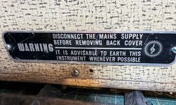
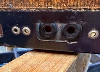
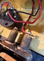
Another thing, I am concerned about is the raw mains connectors. These are wired across the mains and take a British 2Amp 2 pin plug. We haven't used those since 1962. I may disconnect it as the holder for the socket contacts are recessed, making the fitting of a compliant socket, not practical or not sympathetic for the type of equipment it will be fitted to. A standard 13A socket would look unsightly.
What would you do?
A few pictures of what I mean attached.
This will be removed and replaced with a quality connector. I will then make a foot switch with latching contacts.
Another thing, I am concerned about is the raw mains connectors. These are wired across the mains and take a British 2Amp 2 pin plug. We haven't used those since 1962. I may disconnect it as the holder for the socket contacts are recessed, making the fitting of a compliant socket, not practical or not sympathetic for the type of equipment it will be fitted to. A standard 13A socket would look unsightly.
What would you do?
A few pictures of what I mean attached.
Attachments
PelliX
Well-Known Member
What would you do?
Well, I concur on the RCA socket. It looks as if it may have had one rivet replaced at some time - they two ook quite different.
For the mains input I'd first consult the customer, probably. Assuming I have free reign, it depends; can the 'strip' holding the connectors be removed cleanly (i.e. by removing the rivets surrounding it)? If so, then I would remove it and install a more modern replacement into the outer chassis. It's nice that it's recessed in the original setup, but not imperative, I think.
If it isn't possible to cleanly remove only the original AC input then I would likely remove the original connectors and feed a new mains AC flex in through one of the resulting holes, grounding the chassis where applicable and put a strain relief on the inside, etc. Assuming the power switch isolates both the live and neutral wire, that could be done according to code.
OP
Jon Snell
Active Member
It is a mains powered, unswitched auxiliary output. The mains is fed by a standard 3 core cable as it should be. It is the original cable and is in good condition.Well, I concur on the RCA socket. It looks as if it may have had one rivet replaced at some time - they two ook quite different.
For the mains input I'd first consult the customer, probably. Assuming I have free reign, it depends; can the 'strip' holding the connectors be removed cleanly (i.e. by removing the rivets surrounding it)? If so, then I would remove it and install a more modern replacement into the outer chassis. It's nice that it's recessed in the original setup, but not imperative, I think.
If it isn't possible to cleanly remove only the original AC input then I would likely remove the original connectors and feed a new mains AC flex in through one of the resulting holes, grounding the chassis where applicable and put a strain relief on the inside, etc. Assuming the power switch isolates both the live and neutral wire, that could be done according to code.
If my memory serves me correctly, Watkins, they became WEM, and made the Copycat. The very early models, had a 2 core mains lead and I have seen some very early ones, with a 2 pin plug that would probably have fitted into the slot.
I shall ask him if he still has it and if not, suggest I leave it looking as it is and remove the live feed to it in such a way, as to make a restore simple.
Safety is all I am concerned about.