NPBD: RockBoard Tres 3.1

I discovered an access problem regarding the USB port. If there are three pedals behind the MS-3 then access to the USB and MIDI ports are blocked. I'm not too worried about MIDI at this stage, but I need to be able to connect my computer to the MS-3 if I want to use the Librarian software to manage patches. So I ordered a 'left angle' USB cable from the printer style USB in the back of the MS-3 to reach to the hole on the right side of the RockBoard Tres 3.1 (the hole for mounting the Rockboard LED Light accessory), which might need to be enlarge slightly to fit a Neutrik D panel mount LED socket. From there I can run a cable easily to my computer. I have also ordered the Neutrik rubber dust cover to keep the USB port clean.

Here's an idea of the issue with the cable. Annoyingly I couldn't use an 'up angle' cable as there is no hole in the RockBoard there

7uGdoyf.jpg
Every board needs a little customizing!
 
I have had a Rockboard for approx. a year now.

Very happy with it, also got the Rock module? for routing and 4 cm.

Has traveled well, and does everything I've asked of it.

Once you get your details ironed out, think you'll be more than satisfied.

Yes I have the new MOD 5 coming, which has routing for three TRS and a TRS/XLR parallel out, no power input but I've cut the chassis in front of the centre brace and will run a power cable through there to the T-Rex Fuel Tank Chameleon mounted on The Tray. I'm not running the guitar cable into the MOD 5, instead I will run the TRS amp footswitch cable through A, the cable from the MS-3 to the front of the amp through B, the effects loop send from the amp into C, and then run the effects loop return out of the 1/4" parallel out. I generally set up stage left so I will run the cables in that direction, including the power cable, which I will fit a right angled socket to so that I can tuck the pedalboard in close to the foldback speaker so that idiot stage invaders can't step on the cab sim selector on the front of the MOD 5. I am also fitting a panel-mounted Neutrik USB on the right of the board near my tuner and mute pedal, which is where the guitar cable will enter the board. The USB will be connected to the MS-3 and will be useful for setting up patches at home and in the practice room with the Boss software on my MacBook Air.
 
Okay a heap of parts arrived today and I've started fitting stuff. First of all I wound the screws for the MOD 5 into the Rockboard to cut the threads, then I wound them out again and tested the fit of the module. Then I attempted to fit the power cable to my power supply and realised that it needed to be turned around for everything to go in nicely, so I peeled it off the velcro and then put it in the correct position. The IEC socket etc was all good but the rubber boot to go over it was too large and the spade connectors are too clumsy. So I will solder the wires to the terminals and I exchanged the boot for the smaller size. This involved a trip to Jaycar, which quite frankly seemed like it could have better quarantine and I washed it and my hands very thoroughly when I got home. I also flipped the Tray over to the other side and realised that the power supply on the tray fits behind the module without dramas. So I called the local music shop and asked if they had one in stock, which they did, no now I have two. The Rockboard Natural Sound Buffer is slightly lower in profile than the power supply and much smaller in footprint so it will mount on top of a second Tray behind the MOD 5 no worries. The Rockboard buffer was under $50, the best value buffer on the market, and the Tray was $17, so that was cheaper than other options for a small buffer that fits under the board, most of which were over $100 or had to be imported from China (not ideal at the moment).

I cut the end off of a 0.5m angled end IEC cable and I will solder that to the the IEC socket / EMI filter, then put the boot over it. It will run up the centre brace on the board to the power supply.

Here are some photos.

The first is a size comparison of the RockBoard Tres 3.1 and the Pedaltrain PT-2.

IdyrZs7.jpg


Here you see the power cable after I chopped the end off. You can also see the EMI filter, and the angled power cable end that I will fit to my long IEC cable that I run out to my pedalboard at shows. The rubber boot was too large and had to be exchanged

5QUKJE1.jpg


Here's the front of the MOD 5

WgLHioY.jpg


Here's the rear of it

H4V51AZ.jpg


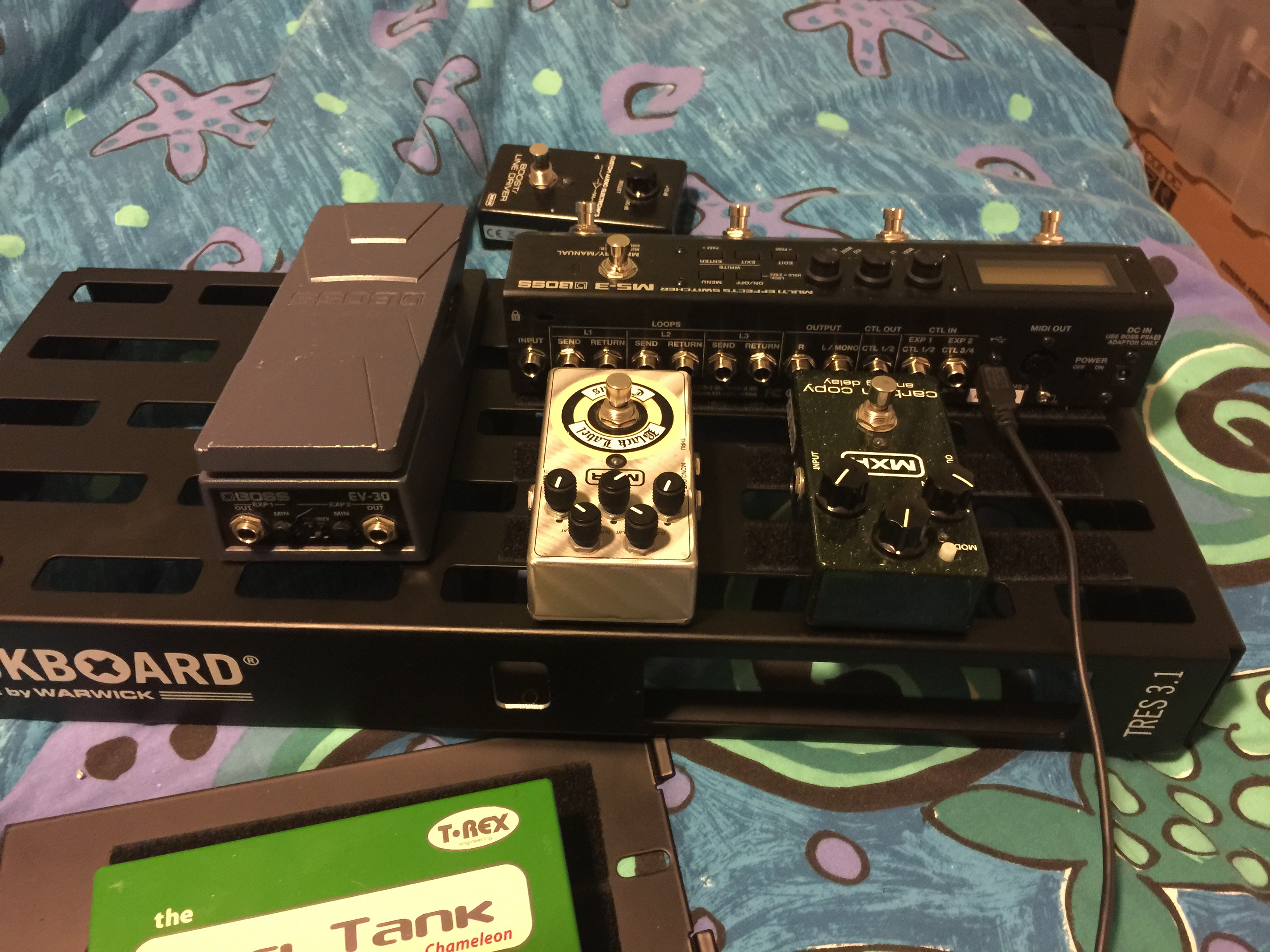
Here you see how the power cable will come out at an angle and run to my right, which suits me as I set up stage left. You also see the MOD 5 mounted into the board

b3W98nU.jpg


Here you see the socket

dgKZSym.jpg


I threaded the cut power cable through the centre brace like this

zcIjgCw.jpg


Here you can see that I reversed the power supply

6aFMPGr.jpg


This routing of the AC power looks neat to me

eJhTL6j.jpg


Here you can see that the Tray with the power supply on it easily fits on the other side behind the MOD 5, demonstrating that there is plenty of room to mount the much smaller buffer that way

BzI8vkU.jpg


More obvious here

WZ8q5v8.jpg


So I bought a second Tray today. Note also the smaller rubber boot

0jbRsve.jpg


I used a razor to remove the covering on the end of the power cable

FtU6dz6.jpg


I managed to get this Boss cable kit old stock, way below current wholesale price

Ow3MjqW.jpg
 
Well today I got my board back from the local engineering workshop with three aluminium risers and the hole on one side enlarged to take a Neutrik USB socket. Then I wired up the AC cable from the front panel IEC socket to the power supply, and installed the USB port with its rubber cover. Then I applied velcro to the new risers and put the pedals on the left side of the board.

gc8tUBx.jpg


LPrNj1o.jpg


eMSl5md.jpg


Q0n1oyP.jpg


mR1jt3x.jpg


cJC511X.jpg


7U7VPC1.jpg


2h7zgwr.jpg


XlczZpo.jpg


bZdkBpo.jpg


u1uhHmM.jpg


eUerUCm.jpg


wOkZ9MG.jpg


CjXDXb2.jpg


yOhv6EY.jpg


iUSNZVi.jpg


lAT22sg.jpg
 
Ha ha i just realised that I installed that rubber cover for my new USB port incorrectly. I saw the word ‘gasket’ and immediately realised what I had done wrong. Fits much better now.

GfPbVQK.jpg


u3ULeVy.jpg
 
Last edited:
A couple more parcels at my post office today, one from Swamp Industries (two Neutrik TRS female jacks and a Moen daisy chain with ferrite beads) and the other from Mannys (Boss FS-7).

The jacks will be used for building 7-pin DIN to TRS adapter cables for my JSX and 6534+ while the daisy chain will be used to power the chorus and buffer, as well as the tuner. Not sure as to whether I should use that for the FS-7 and mute box LEDs as well, and leave the power out on the back of the tuner free for when I use my Morley Dragon 2 George Lynch signature wah (which can just sit by the board before the tuner), or to use the daisy chain included with the FS-7 to power those two. I suspect that the former option is more sensible but the daisy chain that came with the FS-7 is nice. If I have any power-related noise problems with the boost or chorus I will try the other option.

I took two small feet off of the bottom of the FS-7 and added velcro. Boss put the serial number in a stupid place though so I had to work around that, and put extra loop velcro between the rails. I avoided placing the protruding round head screws on top of the rails, so that it would sit tighter and flatter.

The other two photos were taken last night, of the tight fit of the board in the flight case once the MOD 5 module is installed. The selector knob protrudes from the unit a fair way. I would recommend the flight case rather than the soft bag especially if buying one of these modules. Some of the other newer modules are likely to have this issue as well. It fits but I wouldn't like it in a soft bag and if you drop it on that side the plastic knob is the first thing that would hit the floor.

PepONqP.jpg


ttqUagP.jpg


Jm95ZKb.jpg


NdlHCPC.jpg


ywQO2qV.jpg


1viu5V7.jpg


u1PnHKA.jpg
 
Last edited:
I received a RockBoard Natural Sound Buffer in the mail today and also fitted a new angled end to my old 5m straight IEC power cable, together with buying a 5m USB A/B cable to go from my pedalboard to my computer.

I did a really neat and tidy job of the cable, if I do say so myself! I won't be scared to do those again. I also started putting cables on the board so that I can test out the MS-3 in the new signal path, and try out various positions for the buffer.

When I have decided what goes where I will cut new cables from the Boss Cable Kit. I am also waiting on some new TRS cables (for the amp footswitch function, expression pedal, and FS-7, a mute pedal, and a Boss TU-3S tuner that is taking over two weeks to travel 50km via Australia Post ...

NneqV5j.jpg


QTfs6UK.jpg
 
Well I've "installed" most of those 3M cable tie mounts that I bought from RS Components. The blank parts of the rails where they seem to be missing are areas where the power supply and buffer come too close to the rails for them to fit. Cost me $14 with overnight delivery for 100 of them, so I have plenty left over. Note that I bought a second The Tray mounting accessory because I knew I was going to add the Natural Sound Buffer.

With The Tray mounting system on each side, not fixed on yet:

EHJF5cY.jpg


With the two trays turned over to show the positions of the power supply and the buffer:

5SWNcb9.jpg


The row of cable tie mounts behind the vertical front surface are for securing the USB cable. I might add others along the edge to secure various power cables. There is one out of view securing the large AC power cable.

0Dlo44H.jpg
 
A couple of hints: don’t stick down cable tie mounts too early, because you’ll end up with a spatula, paper towel, and metho trying to get half of them off! Second, if you buy one of those Moen daisy chains with the ferrite beads know that they are bulky and routing the daisy chain through tight spaces can lead to profanity. The board is coming along well though; just waiting for a couple of parcels from Loopi: three TRS patch cables and a tuner/mute pedal
 
This has been a slow process but also a learning process. The daisy chain is okay but I am going to have to attach it into the edge of the board with cable ties so that it doesn't foul the power supply, which I have had to mount as close as possible to the edge of the board so that I can fit the buffer under the same side. I also had some success with the Boss cables today, at least the one I finished works, although I will say that I am glad I initially cut it too long, because I had to redo the ends a few times. Basically stretch the outer casing, cut the wire straight, twist it into the terminal, and screw the grub screw in until it is flush with the outside of the terminal fitting.

Here are some photos. I didn't get one of the bee whose winkie was trapped between the buffer and the power supply, he flew away but did call out some begrudging thanks as he buzzed off.

QcXtEqz.jpg


JaV6rXj.jpg


TlokUZt.jpg


VVBDHnj.jpg


QVHxnJD.jpg


ygLalLO.jpg
 
Back
Top