Marshall Valvestate Bi-Chorus 8200 Resource Thread:

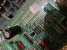
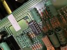
Should have changed all electrolytic caps, preamp and power amp.
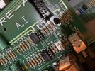
Should have replaced effects loop jacks.

The reason being that the electyrolytics fail with age, and the PC mount caps are not particularly long lasting to start with.

The effects loop jacks contain a switch which breaks the signal path.
When the jacks are old, a lot of oxide has built up on the switch contacts eventually causing the signal path to drop out.
Cleaning the contacts is temporary. Replacing the jacks is really the only long lasting solution.

With those in mind, better to do both when the amp is serviced to reduce future failures /maximize long term reliability.

Sure, I can see the logic in your recommendation, but I feel like we did a good repair and cleaned/inspected what we didn't replace.
 
Sure, I can see the logic in your recommendation, but I feel like we did a good repair and cleaned/inspected what we didn't replace.
When Marshall started making PCB amplifiers, they stopped using longer life caps.
The PC mount caps they used last about 1/2 as long....
I like to change them to 10,000 hour 105C rated.

In most amplifiers today they are using 2000 hour caps.
 
Excellent point!!!!

When we say "2000"hour cap
we mean:
2000 hours "is" measured at full rated voltage, and full rated temperature.

If we reduce operating voltage below max rating,
and we reduce actual operating temperature below max rating,
the life becomes longer exponentially.

What I'm trying to say is
A 2000 hour cap lasts much longer when operated well below max temp/voltage ratings.

"...degradation and failure of electrolytic capacitors is slow evaporation of the electrolyte over time, and of course, this is made worse at higher temperatures. This results in lower capacitance and higher effective series resistance (ESR). It’s a bit of a vicious circle because as ESR rises, so does any self-heating effect due to ripple currents...."

"..You can achieve a decent lifespan increase when the operating voltage is lower than the maximum rated voltage. The most conservative estimate is that lifespan doubles when the component is operated at 50% of the rated voltage. Of course, it becomes proportionately smaller as the operating voltage gets closer to the maximum rated voltage..."
 
Last edited:
Hi all, I’ve been reading this whole thread since last night, I’m currently repairing a 8200 for a friend, he brought it and it was not sounding.
I plugged in the front = no sound and the fx return = no sound
Inspected the caps of the power section they’ve swollen, replaced electrolytic caps and to be sure the electrolytic caps in the preamp as well. Sound came back and the amp sounds amazing, an easy fix I thought. Upon inspection for all the channels I found that if I max out the treble in the OD ch the sound is cut almost completely, I’ve been checking all the component and replaced some some resistors and caps for this channel but the problem still remains, sorry don’t have a scope. Attached is the offending pot, I have swapped it for one of the same from the clean channel but didn’t have any effect

Cheers
 

Attachments

Hi all, I’ve been reading this whole thread since last night, I’m currently repairing a 8200 for a friend, he brought it and it was not sounding.
I plugged in the front = no sound and the fx return = no sound
Inspected the caps of the power section they’ve swollen, replaced electrolytic caps and to be sure the electrolytic caps in the preamp as well. Sound came back and the amp sounds amazing, an easy fix I thought. Upon inspection for all the channels I found that if I max out the treble in the OD ch the sound is cut almost completely, I’ve been checking all the component and replaced some some resistors and caps for this channel but the problem still remains, sorry don’t have a scope. Attached is the offending pot, I have swapped it for one of the same from the clean channel but didn’t have any effect

Cheers
What you want to do is test for DC offset at pin 6 of the 5534 op amp....
If there is not zero volts on pin 6, replace the op amp.
The output of the opamp should be very close to zero volts DC.
 
checking the DC voltage in the IC1 I got the following:

Pin #:
1: -12v Balance
2: 0v inverting input
3: 0v non-inverting input
4: -12v v-
5: -12v compensation
6: 0v output
7: 12v v+
8: 0v Balance/compensation

Is pin 5 ok with the -12? I happen to have a replacement 5534 in my spares, I know they are equivalent but the one in this amp is actually a TL071
 

Attachments

checking the DC voltage in the IC1 I got the following:

Pin #:
1: -12v Balance
2: 0v inverting input
3: 0v non-inverting input
4: -12v v-
5: -12v compensation
6: 0v output
7: 12v v+
8: 0v Balance/compensation

Is pin 5 ok with the -12? I happen to have a replacement 5534 in my spares, I know they are equivalent but the one in this amp is actually a TL071
The best way to change an op amp is to put a socket in first...
also does the op amp get hot?
I would check to see that C10 C11 C12 are blocking DC voltage from the cathode follower of the 12AX7.
If DC is bleeding thru 10 11 12 that would explain why.
 
The best way to change an op amp is to put a socket in first...
also does the op amp get hot?
I would check to see that C10 C11 C12 are blocking DC voltage from the cathode follower of the 12AX7.
If DC is bleeding thru 10 11 12 that would explain why.
Yes, as part of my initial assessment, after changing the electrolytic, I went and changed most parts for this section with no effect.
The parts changed were: r16, r17, r19, r20 and then
C10, c11 and c12 were changed, I don’t have a replacement for c9 in my spares, and that’s the only bit I haven’t changed.
The dc is blocked for sure.
 

Attachments

Yes, as part of my initial assessment, after changing the electrolytic, I went and changed most parts for this section with no effect.
The parts changed were: r16, r17, r19, r20 and then
C10, c11 and c12 were changed, I don’t have a replacement for c9 in my spares, and that’s the only bit I haven’t changed.
The dc is blocked for sure.
Try changing the op amp...
 
Try changing the op amp...
I will source the socket today, I doubt the electronic store I go has the mili-spec, but I know they have the normal ones. I’ll check mouser or RS but the shipping is the issue, as I’ll ask my friend (the owner of the amp) what he wants to do and take it from there.
If it was for me, the mili-grade would be the way to go, specially how this amp vibrates on top of the cab when dimed.
I was buying those production sockets for 5 cents each. It's up to 18 cents now.
Jameco electronics

The Mill-max costs $1 each.
 
Last edited:
I was buying those production sockets for 5 cents each. It's up to 18 cents now.
Jameco electronics

The Mill-max costs $1 each.
49 cents for a better socket. Same vendor.

 
I was buying those production sockets for 5 cents each. It's up to 18 cents now.
Jameco electronics

The Mill-max costs $1 each.
So I went and asked if they had military grade, their answer was simply, there’s cheap and there’s expensive .
Got the expensive, they were about 0.89aud, so I got 5 and 1x 14pin.
Got home mounted them, changed the 5534, and put back all the 5201a’s and the LM348N the issue is still there.
I got the suspicion that it’ll be c9 that is a 4.7nF cap that looks like a resistor, it is directly connected to the treble pot to ground and it is the only component I haven’t change in that section
 

Attachments

Back
Top