OP
marshalltsl
Well-Known Member
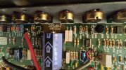
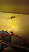
It's a stock EL34 JCM900. 2,2K 5W resistors.We have to identify the amp better.
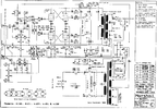
Is C15 connected from pin 1 to pin 6 of the phase inverter?
There are 2 different schematics, the part numbers on the 2 boards are different.
We need to find out which one you have.
On the rear circuit board, there are 4X 5 watt big resistors.
Each 5 watt resistor connects to pin 4 of a power tube.
Are these 4 large (5 watt) resistors 470 ohm or 2.2 K ohm?
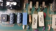
These amps came stock with either 5881 tubes or EL34 tubes.
The resistors tell you which version you have.
People often change them to different tubes....that's why we need to look and see "if" it's been changed.
Once we see which board you have and how it is set up, for which tubes...original or changed?
Then we know more.