OP
marshalltsl
Well-Known Member
Without tubes. No standby switch on. No operate.
V1 pin2 3,4Vac.
Pin5 -37,2 Vdc.
Pin7 3,4 Vac.
Pin3 & 4 340Vdc
V2 pin 2 3,4 Vac.
Pin5 -37,2 Vdc.
Pin7 3,4Vac.
Pin3 & 4 340Vdc
V3 pin 2 3,5Vac.
Pin 5 -37,2 Vdc.
Pin 7 03,5Vac.
Pin3 & 4 340Vdc
V4 pin2 3,5 Vac.
Pin5 -37,2 Vdc.
Pin7 3,5 Vac.
Pin3 & 4 340Vdc
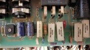
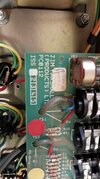
Doing this mesuraments I saw R30 from rear board with voltages arc flashes on It.

V1 pin2 3,4Vac.
Pin5 -37,2 Vdc.
Pin7 3,4 Vac.
Pin3 & 4 340Vdc
V2 pin 2 3,4 Vac.
Pin5 -37,2 Vdc.
Pin7 3,4Vac.
Pin3 & 4 340Vdc
V3 pin 2 3,5Vac.
Pin 5 -37,2 Vdc.
Pin 7 03,5Vac.
Pin3 & 4 340Vdc
V4 pin2 3,5 Vac.
Pin5 -37,2 Vdc.
Pin7 3,5 Vac.
Pin3 & 4 340Vdc
Doing this mesuraments I saw R30 from rear board with voltages arc flashes on It.
Last edited: