STRefugee
Well-Known Member
Hello!
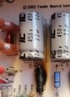
My old Blues Junior (2002) is in need of attention. Pls see the attached pic. I understand that fried-up resistor to be a 2.2k/2W.
Would this be a suitable replacement?
After running some search online I came across a few historical chats relating to this issue.
It is said to act as a supply dropper on the power supply circuit feeding output tubes.
Could be because Bias Voltage setting on the power valves is too low.
I just want to fix it. I don't really want to go into 'mod kit' mode and all that. Just getting it back in service with the simples easier fix will do.
Please do share your thoughts, suggestions as to how I may fix this.