2204 clone gut job

Getting heater glow on the power tubes, but nothing on V1, V2 & PI.
Voltage reading 2.7 on the heater wiring at all the sockets.
What was your AC voltage at the wall when you just fired it up?

Unless in a dark room, some preamp tubes hide the filament light more than others.

2.7 vac is definitely not good enough!

Sometimes I have accidentally left a voltage draining circuit attached to the amp's circuit after I fired it up!
 
What was your AC voltage at the wall when you just fired it up?

Unless in a dark room, some preamp tubes hide the filament light more than others.

2.7 vac is definitely not good enough!

Sometimes I have accidentally left a voltage draining circuit attached to the amp's circuit after I fired it up!
I'm right at 120v.
Preamp tubes are JJ 803s long plates. They have a noticeable glow.
I guess I'll have to disconnect the leads and check the no-load voltage.
Can also check the socket wiring for shorts when the transformer is out of the circuit.
 
Unless maybe I misunderstood your notes there.
Are you saying that while the mains power was provided you measureed 3.3VAC to gound on each leg then that is different that would be 6.6VAC leg to leg. But this is still an unloaded measurement. so you can still have the heater winding issue.
 
Unless maybe I misunderstood your notes there.
Are you saying that while the mains power was provided you measureed 3.3VAC to gound on each leg then that is different that would be 6.6VAC leg to leg. But this is still an unloaded measurement. so you can still have the heater winding issue.
From what I remember, I was told those readings were ok.

I'm not opposed to a new PT.
I'm having fun and learning a lot from this series of unfortunate events. :rolf:
All in, I'd still be under budget from a straight up Mojotone kit + loop.

Best deal I can find is from my go-to, Amplified Parts.
Free shipping, $180 for the stand up, $10 more for the lay down.

1784416732097.png
 
Do you have a variac? You could test the amp removing only the heater connect and use the variac at 6.3VAC only for the heaters and see if the amp comes alive. That would pretty much verify it beyond question. then buy the new PT. You know a variac even a cheap one would be cheaper and you would finally have one.

Always look on the bright side of life, Wer wer...wer wer.wer wer. wer wer. :flash:
 
Last edited:
Before firing the parts cannon I would recommend solid testing. Assuming the heater winding reads about 3.3V from each leg to ground (and the centertap is connected the ground obviously) then connect an 8 ohm resistive attenuator. The AC voltage should not drop as it would draw about 0.7A. Drop to about 2 Ohms for 3A current, but any winding issues would typically show under a modest load such as when using 8 Ohms. Obviously, if you have other suitable resistors - even better.
 
Before firing the parts cannon I would recommend solid testing. Assuming the heater winding reads about 3.3V from each leg to ground (and the centertap is connected the ground obviously) then connect an 8 ohm resistive attenuator. The AC voltage should not drop as it would draw about 0.7A. Drop to about 2 Ohms for 3A current, but any winding issues would typically show under a modest load such as when using 8 Ohms. Obviously, if you have other suitable resistors - even better.
I have a 100w 8Ω resistor on the amp stand for a test load.
Haven't bought anything else yet.
Going to retest the PT and see if anything has changed.
 
Reading 3.2 VAC on either leg.
0.3 Ω to ground, but I also get 0.3 Ω just touching my meter leads together, so there's that...

Zero resistance from V1 to V5 on both heater wires, no continuity to ground, so I don't think it's my wiring.

IIRC from the feedback on the MF thread, there's a degree of unknown about the load that Hammond organ PT can handle.
Some specs say it don't got the balls, some say it does.
 
So, run each leg through an 8Ω resistor?
Put the 100w 8Ω between the two legs of the Heater winding. The center tap should also be grounded, It should draw about 0.825 amps at 4.45 Watts, the Voltage on either end of the resistor should still hold at 3.2VAC to ground. If it drops then the winding can't handle the full operating load with the 5 tubes which would normally pull about 3.9 Amps assuming EL34x2 ouput and 12AX7x3 preamp.

The loop is powered by the HT/B+ so this test does not indicate anything about that loop.
Please employ good safety techniques, one hand in pocket etc.
 
The resistive attenuator @PelliX is referring is designed like a thermistor or a LBL except you can keep adding more resistance or take away resistance. As the voltage is applied more and more current is allowed up to a maximum depending on design. This puts more and more current load on the Heater winding to give a more realistic full test.

If you are having fun testing this out you could build a device that holds all 5 tubes and plug them in one by one and test the heater winding voltage until...you see it drop. If it doesn't then it is not the heater winding.

If we knew everything was working properly on your amp you could do this using the amp itself. Keep standby open and add tubes until you see the heater voltage dropping. We do know that it was all the way down to 2.9 when you fired it up, and the HT was low as well

You did just verify continuity through both legs of heater tube wiring and no continuity to ground, so it could be a good test to try. It would be a real world test of your situation.

FYI the HT winding will typically drop as the heaters warm up too and your HT was going too far down as well.

I know this might sound frustrating after having pulled your PT out, it is ironic but remember we still don't know what the actual issue is. Troubleshooting can be a real PITA at times.
 
Last edited:
I have a 100w 8Ω resistor on the amp stand for a test load.

Would do the trick. It's just about putting a simple load across the heater winding. The resistor won't dissipate more than about 20W anyway. If the voltage doesn't collapse with that resistor attached, I severely doubt there's anything wrong with the PT in that respect.

Reading 3.2 VAC on either leg.
0.3 Ω to ground, but I also get 0.3 Ω just touching my meter leads together, so there's that...

3.2V is a little low unloaded, but alright. The resistance to ground is logical; the heater winding is centertapped and referenced to ground. The relatively small winding itself has practically no DC resistance - that's fine.

Zero resistance from V1 to V5 on both heater wires, no continuity to ground, so I don't think it's my wiring.

Presuming that the PT is connected, you should measure continuity to ground there - heater pins should all measure exactly the same as the winding itself, give or take a couple of Ohms.

The low output voltage is a little confusing though. We may have gone over this, but I no longer have access to the MF; you've confirmed the correct primary is being used (110, 120V, etc), right?
 
I know this might sound frustrating after having pulled your PT out, it is ironic but remember we still don't know what the actual issue is. Troubleshooting can be a real PITA at times.
Not in a hurry, I have a few other amps that still work...
So far, I just disconnected the 2 heater supply wires (and the loop).
Presuming that the PT is connected, you should measure continuity to ground there - heater pins should all measure exactly the same as the winding itself, give or take a couple of Ohms.
I can reconnect the heater leads after the 8Ω test and verify
you've confirmed the correct primary is being used (110, 120V, etc), right?
None of that wiring has ever changed from the way it was when I got it.
Same connections to the power and standby switches (other than adding the standby fix)
3.2V is a little low unloaded, but alright.
If the power supply to the tube heaters is low, but acceptable, could the problem be "downstream"?
It's gotta go somewhere to be a circuit, right?
 
I can reconnect the heater leads after the 8Ω test and verify

Yup, good call. If the voltage doesn't drop significantly with that resistor, chances are the heater winding itself is alright.

None of that wiring has ever changed from the way it was when I got it.
Same connections to the power and standby switches (other than adding the standby fix)

OK, but that doesn't actually mean it was done correctly. Clearly the guy who assembled the amp wasn't one of the world's greatest engineers - and even those make mistakes.

If the power supply to the tube heaters is low, but acceptable, could the problem be "downstream"?
It's gotta go somewhere to be a circuit, right?

Well, yes and no. The unloaded voltage will always be higher than loaded. Typically a 6.3V winding will read about 6.8-ish unloaded or so, varies somewhat from transformer to transformer. Effectively you're putting a ~10MOhm load on it when you measure it with a DMM, that's not enough to really bring it into 'operation' like the resistor should. IF the voltage sags heavily under that test, there's something wrong with the PT and there's no use hunting downstream. If the PT behaves correctly, then yes - something is amiss in the circuit.

1784464066111.png

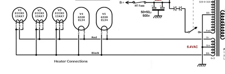
Note that every single heater pin listed there *should* read as a near short to ground.
 
Note that every single heater pin listed there *should* read as a near short to ground.

Adding for clarity; *without* the transformer connected, those pins should all be floating, i.e. *not* connected to anything. While you have the PT disconnected, check that, too.
 
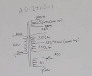
I found this on one of my searches about that PT.
It was in an old for sale listing for this model# transformer.

Screenshot 2026-05-02 082433.jpg

There is an unused secondary pair taped off.
I'm assuming it's the 5v shown.
 
Back
Top