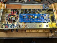
2204 clone gut job

Here's a nice 2204 starter kit if anyone is interested...
It even comes with a few extra parts. :yesway:

View attachment 111708

Seller states has a known volume drop when hot. modded tube fx loop
What are the potential causes of that, addons welcome:
Heater intermittent voltage drop - PT htr winding
Doubt the extra 12ax7 heater current as these had the same drakes for the 2205 which had 5 preamp tubes.​
shorting OT if run hot into an attenuator.
output Tube failing if never replaced and run at mid to lower bias weak output when hot.

These things can be a roll of the dice but you could also be lucky, who knows what other mods were made or if done improperly.

I think it would be cool to get one of these combo chassis and put a mirror faceplate on it in a head cab. So it reads backwards but right side up. :)
 
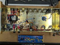
Rebuild underway.
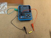
Tested each part with the gizmo.

gut job (19).jpg

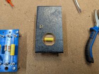
Made a quickie bending jig with some scrap wood.

gut job (20).jpg

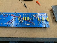
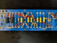
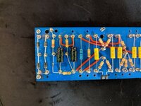
Populating the board.

gut job (21).jpg

Went back and trimmed all the long legs after getting everything positioned.
Soldering everything in to keep it place.

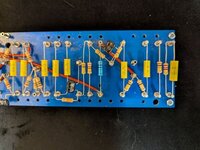
gut job (22).jpg

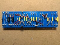
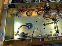
Replaced all the pots, tube sockets, filter caps and fuse holders on the chassis.
Temp mounted the board so I can cut all the leads to length.

gut job (23).jpg

I think that's it for today.
 
I like the gizmo and the home made quickie bendy thingy. (y)

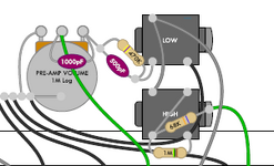
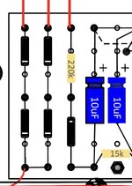
I assume the 470pf treble peaker/470kR will be on the input to pot?

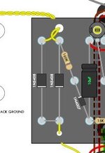
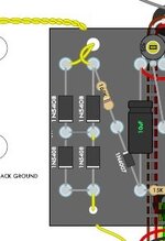
I know it isn't necessary, curious why you don't use the dual diode rectifier?

It all looks good so far, lots of work quickly, great symmetry too:flash:
The gizmo is reassuring for my level of incompetence. :rolf:

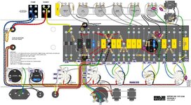
I'm following the Mojotone wiring diagram for the '78 JMP 2204. (attached)

Yes?, 470k / 500pF parallel on the input.

1783865541417.png

@pdf64 had mentioned the dual diode rectifier in a trouble shooting thread on the forum "that shall not be named".
I have the 2 from the old layout I could add in - now would be the time.
Also have some turrets I can add.
Would I just run them in series?

diode.jpg dual diode.jpg
 

Attachments

Got a few more things out of the way.

gut job (27).jpg

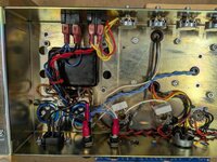
Re-wired the connections to the power socket.
Wired the connections to the new fuse holders with spade connectors.

gut job (28).jpg

Wired in the PT, OT, choke and filter cap ground connections.

gut job (29).jpg

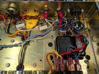
Ran the heater wiring and rewired the input jacks.

gut job (30).jpg

I think I got to a good point to start doing all the board leads, but that'll be another day...

gut job (31).jpg
 
Ran the heater wiring and rewired the input jacks.
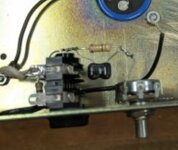
gut job (30).jpg
I feel very nitpicky this morning…

IMG_2764.jpeg
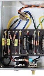
I would tighten up that treble peaker circuit between the input jacks and gain pot. Unwanted noise induced at signal wires benefit from being short as reasonably possible.

A nice example from Michael Mortimer of Modulus Amplification:
IMG_2765.jpeg
 
I feel very nitpicky this morning…

View attachment 111923
I would tighten up that treble peaker circuit between the input jacks and gain pot. Unwanted noise induced at signal wires benefit from being short as reasonably possible.

A nice example from Michael Mortimer of Modulus Amplification:
View attachment 111924
The thought crossed my mind to rotate the low input so the solder lugs were on the pot side like the pic above.

If you think it will reduce noise, that's an easy change - and now's the time before all the pot leads go in.

Thanks for the "input". :yesway:
 
Then the 1nF disk between the pot middle lug and the lug you have the 470pF/470kR going to now, like the blue one in the above pic.
That is just a reminder...The shorter the leads the better, not only helps the noise but also from gravity or accidental touching other components or wires as you need to tuck things away in that small space.
 
Got a little bit done tonight after work.

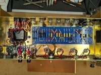
Wired in the preamp filter cap and mounted the board.
Ran most of the wiring on the pot side.
Flipped the low input and shortened up the resistor/cap leads.
Still need to finish connections to V1, loop to MV, and the external bias trim pot.

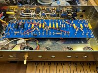
gut job (32).jpg

I should be able to wire up the rear panel and tube socket side tomorrow.
Hoping to get to the point of hooking it up to the LBL for some preliminary voltage readings.

gut job (33).jpg

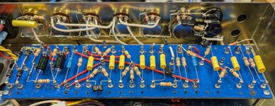
Higher resolution crop - click to enlarge.

gut job (33)x.jpg
 
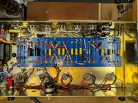
Welp, I got everything hooked up...
(fairly sure)

Pic showing tub socket wiring.

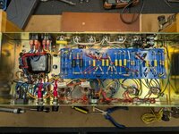
gut job (34).jpg

Final with bias trim, speaker jacks & loop.

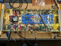
gut job (35).jpg


Tried the LBL and nothing started smoking or blowing fused, so I went full power (120v)
Getting heater glow on the power tubes, but nothing on V1, V2 & PI.
Voltage reading 2.7 on the heater wiring at all the sockets.

Here's voltages across the board compared with the Mojotone target amounts.
Was getting closer to 440v after the rectifier with the old guts, now reading about 410v
Low readings just about everywhere - any thoughts?

Voltages.jpg
 
Is this the same PT that was in the original? I remember you were getting inconsistent readings on your heater before, is that right?
 
Is this the same PT that was in the original? I remember you were getting inconsistent readings on your heater before, is that right?
Inconclusive.
PT tested fine with no load.
Found a grounding problem and the amp was working, until it didn't.

I'm going to pull the loop.
 
Back
Top