
You are using an out of date browser. It may not display this or other websites correctly.
You should upgrade or use an alternative browser.
You should upgrade or use an alternative browser.
2204 clone gut job
- Thread starter fitz
- Start date
OP

fitz
Ambassador of DIY

I think I did that. Post#51.Adding for clarity; *without* the transformer connected, those pins should all be floating, i.e. *not* connected to anything. While you have the PT disconnected, check that, too.
Zero resistance from V1 to V5.
No short to ground.

PelliX
Well-Known Member

3.1 VAC on both heater leads with 100w 8 ohm resistor connected between them.
Right, that's a bit low. It's not going to do filaments any favors but it's technically within spec (presuming the voltage remains stable under the full ~3A load). At least it didn't sag like crazy, so that's good.
I think I did that. Post#51.
Zero resistance from V1 to V5.
No short to ground.
Gotcha, OK. Then the PT really just is on the low side or the meter is reading low. A fresh battery or a crosscheck with another meter might be worthwhile before moving on.
If this is really how the PT behaves, then it may have a damaged primary winding, rendering the secondary voltages lower.
This is a bit of a judgement call. You *could* use this PT and just accept the slightly lower voltages. You could also get a new, known good one and forget the whole problem. One consideration are the valves in the amp; lower filament voltages are not beneficial and can/will cause wear faster because they'll be operating slightly under temperature. The choice is yours, obviously.
OP
fitz
Ambassador of DIY
Ok, so why am I getting heater glow on the power tubes, and none on the preamp?This is a bit of a judgement call. You *could* use this PT and just accept the slightly lower voltages.
Ok, let's say the PT is a bit off, but should be functional.IF the voltage sags heavily under that test, there's something wrong with the PT and there's no use hunting downstream. If the PT behaves correctly, then yes - something is amiss in the circuit.
I honestly don't think it was the source of previous issues, and it seems to be clearing the pass/fail tests.
Then what?
Could the 2.7v heater reading under power and load be because of something other than the PT supply?
The meter is reading voltage because I'm giving it a path to ground.
Why aren't the tubes lighting up?
PelliX
Well-Known Member
Ok, so why am I getting heater glow on the power tubes, and none on the preamp?
Are they all connected in parallel as shown on that official 2204 schematic snippet I posted? If so there's a broken wire, bad solder joint or an error in the connections. Do the preamp valves get warm or remain stone cold? Bad sockets, pins, contacts are all possibilities but it's far, far more likely to be an issue with the wiring if *all* the preamp valves are dead.
Ok, let's say the PT is a bit off, but should be functional.
I honestly don't think it was the source of previous issues, and it seems to be clearing the pass/fail tests.
Agree.
Could the 2.7v heater reading under power and load be because of something other than the PT supply?
Well, for the voltage to drop that far you would really, really have to load the circuit (winding) of the transformer. At that point one would hope a fuse would blow as it would incur damage likely and the PT would get "effin" hot after a short while.
The meter is reading voltage because I'm giving it a path to ground.
Why aren't the tubes lighting up?
Well, the meter is a 10 or 11MOhm path to ground. At ~3V that's practically zero current, not worth even considering. I can't zoom in (much) on the pictures showing the heater wiring. Sure you have the right pins...? If you measure the resistance of the filament in the valves themselves (out of circuit) they should register as very low, right?
OP
fitz
Ambassador of DIY
Wired per the Mojotone diagram.Are they all connected in parallel as shown on that official 2204 schematic snippet I posted? If so there's a broken wire, bad solder joint or an error in the connections.
Resistance from V5 to V1 is no more than the meter leads.
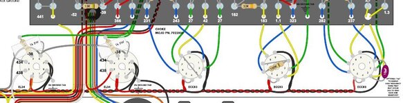
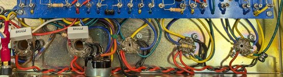
Where are those electrons supposed to go after the party in the tube heater?
I think they're finding the way in, but can't find their way out...
Attachments
PelliX
Well-Known Member
Wired per the Mojotone diagram.
Resistance from V5 to V1 is no more than the meter leads.
Roger, that looks fine. V2 looks to have the jumper between pins #4 and #5, but even if it didn't V1 and V3 would heat up, it's probably just hard to see on the pic. All good.
Where are those electrons supposed to go after the party in the tube heater?
This rabbit hole isn't bottomless, but it's deeper than one might assume, haha. In this case you're dealing with AC so the electrons are actually waiting to bound back and forth into the filament and out again sixty times a second. So, actually, they're not getting in in the first place if nothing happens.
If you measure the resistance of the filament in the valves themselves (out of circuit) they should register as very low, right?
^ Are you sure the valves are OK? I have a ruler on my workbench that says "If you can't find the problem, you're looking in the wrong place". Many a time I have looked at it and nodded.
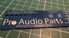
Do you measure about 6V-ish between pins #4 - #9 on any of the preamp sockets? If there's voltage, either the pins aren't making a solid contact or the filaments are not working... nothing else to it.
On a total sidenote, I might shorten the leads on that cap mounted to V1's socket. If it's quiet, fine, but if you get any noise from there, that would be my first port of call.
OP
fitz
Ambassador of DIY
I haven't tried other tubes.^ Are you sure the valves are OK? I have a ruler on my workbench that says "If you can't find the problem, you're looking in the wrong place". Many a time I have looked at it and nodded.
Yes, I know tubes can fail at any time and for no reason, but all 3?
6.2v on V1 & V3 (V2 is under the loop board - atm).Do you measure about 6V-ish between pins #4 - #9 on any of the preamp sockets? If there's voltage, either the pins aren't making a solid contact or the filaments are not working... nothing else to it.
So pin contacts or all bad tubes?
Sockets are all brand new, tubes all worked a week ago - could it be a simple as a shot of Deoxit?
PelliX
Well-Known Member
Yes, I know tubes can fail at any time and for no reason, but all 3?
Matter of exclusion. Bad contacts on three sockets is an even less likely scenario. Just slap a meter across the valve pins. If you read infinity, you have a/your problem. The filament is just a piece of wire and should have a relatively low resistance, under 100 Ohms.
6.2v on V1 & V3 (V2 is under the loop board - atm).
Wicked, then we've narrowed it down a lot. I'm guessing the valves or dodgy contacts indeed.
The only way I could explain all three filaments being destroyed would be a mishap somehow introducing a higher voltage into the circuit while the output valves were out (though they're also a little tougher, electrically). You can take a filament out in an instant with high voltage. Not accusing anyone even remotely or pointing fingers - just sherlocking away...
OP
fitz
Ambassador of DIY
Deoxit in all the sockets, still nothing.
Swapped to a set of JJ 83S tubes..., IT'S ALIVE!
LOL & SMH...
Never had 3 preamp tubes fail simultaneously from sitting in a box for a week.
Last thing I would have suspected.
Sounds f-ing glorious.
Only played for a few minutes.
Dead quiet on high & low inputs.
Preamp & MV working as they should, and never quite did correctly before the rebuild.
Going to re-attach the loop.
Swapped to a set of JJ 83S tubes..., IT'S ALIVE!
LOL & SMH...
Never had 3 preamp tubes fail simultaneously from sitting in a box for a week.
Last thing I would have suspected.
Sounds f-ing glorious.
Only played for a few minutes.
Dead quiet on high & low inputs.
Preamp & MV working as they should, and never quite did correctly before the rebuild.
Going to re-attach the loop.
PelliX
Well-Known Member
Never had 3 preamp tubes fail simultaneously from sitting in a box for a week.
I mean, not that it matters, but any guesses as to what happened? Where they previously in this amp?
Sounds f-ing glorious.
Only played for a few minutes.
Dead quiet on high & low inputs.
Preamp & MV working as they should, and never quite did correctly before the rebuild.
Awesome sauce!
Going to re-attach the loop.
I would also confirm the heater supply is at least 6V or better with the full complement installed - might as well while you're in there, right.
EDIT: I see you did this. 6.2V is alright.
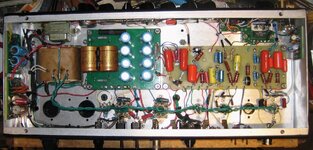
Just thinking aloud; the cathode follower will stress the h/k insulation, and has been known to cause issues with Russian CP valves. The JJs in there should handle it better. That's just a blind stab at what might have happened.
Last edited:
OP
fitz
Ambassador of DIY
Not a clue.I mean, not that it matters, but any guesses as to what happened? Where they previously in this amp?
Yes, these were the tubes in before the rebuild.
Perhaps they got fried the last time I tried to use the amp.
It was giving me trouble and doing strange things.
At this point, I can only speculate as to what was going on from the original build and chassis transplant.
Not regretting the rebuild for now - fingers crossed until I put it through some action.
Loop is installed and working fine with a patch cable switching the bypass on/off.
Gotta hook up something to see how it reacts to some effects.
Thank you for your assistance.

I may have accidentally learned a few things.
PelliX
Well-Known Member
I will never use Belton tube sockets had the octal ark between the pins switched to mil spec ceramic tube sockets
that was a hard issue to troubleshoot
I had to read that a couple of times to figure out the punctuation. What was the potential between the two affected contacts?
Perhaps they got fried the last time I tried to use the amp.
It was giving me trouble and doing strange things.
... this would at least dovetail with what we're seeing here, yup. Potentially heater/cathode insulation (or other) breakdown on V2 leading to a condition taking out all preamp valve filaments. Rare but not impossible. One thing is certain, there must have been a common cause.
Thank you for your assistance.
Anytime.

I may have accidentally learned a few things.
Happens. Just put them with the rest...

67plexi
Ambassador of Amps
On the octal pin 6 DC and pin 7 AC inside the Belton socket then pin 8 to ground when I cut up the socket with my band saw
you could see the black burnt between the pins after tubes failed I put a fuse on the center tap saved the power transformer.
live and learn every vintage Marshall I own used ceramic tube sockets on the 9 pin.
you could see the black burnt between the pins after tubes failed I put a fuse on the center tap saved the power transformer.
live and learn every vintage Marshall I own used ceramic tube sockets on the 9 pin.
PelliX
Well-Known Member
The arc distance depends heavily on the voltage amongst other things, that's why I was curious as to the potential between the two points.
A little hard without punctuation, but pin #6 is not used on the octal valves typically found in guitar amps though it may be used as a tie-point. So was the arc between #6 and #7 or #7 and #8?
Spacing is tighter on the novals but the voltages are typically lower, too, of course.
On the octal pin 6 DC and pin 7 AC inside the Belton socket then pin 8 to ground when I cut up the socket
A little hard without punctuation, but pin #6 is not used on the octal valves typically found in guitar amps though it may be used as a tie-point. So was the arc between #6 and #7 or #7 and #8?
live and learn every vintage Marshall I own used ceramic tube sockets on the 9 pin.
Spacing is tighter on the novals but the voltages are typically lower, too, of course.
OP
fitz
Ambassador of DIY
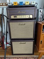
Got it in the shell and put it through some paces.
Everything seems to be working the way I'd expect.
I hooked up the Boss board because it can be problematic with some amps, but it's working fine.
Even with the NS-2 off, the drive pedals out front & EQ in the loop aren't too bad with noise.
With the gate on, the whole set up is quiet.
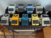
Everything seems to be working the way I'd expect.
I hooked up the Boss board because it can be problematic with some amps, but it's working fine.
Even with the NS-2 off, the drive pedals out front & EQ in the loop aren't too bad with noise.
With the gate on, the whole set up is quiet.




DirtySteve
Ambassador of Hold My Beer
Congratulations!!! 