Amp Mad Scientist
Ambassador of Heresy
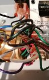
nice jobAlmost there...
View attachment 106041
nice jobAlmost there...
View attachment 106041

Don't panic it's probably just a minor thing.All wired-up and all. Powered it up and switched it on and Fack all!! Not even the pilot light come on.
Tested the cable to the power socket and it's fine.
Tested the switch and the power flows through from S1A to S2A.
No juice flowing anywhere after that it seems. Testing the caps shows zero V readings.
Here's a pic of my nice useless pcb.
View attachment 106088
Spent so much time on this F#£@!! Thing I'm totally fed-up with it now. Better move away from it or I may kill myself stupid.
Take a day off and relax.
take your time don't panicHi @Amp Mad Scientist,
I followed your advise and took the day off. Cooked a lamb tagine with prunes and lots of good stuff for 6 although there were only three of us round the table. Enjoyed a couple 2019 St Emilion bottles and later visited the local Pub for a chilled pint of Italian lager. Crashed in bed and landed a couple of hours from my Cosmic voyage.
Found the will power to get back into my Blues Jr. and I think I might have a cue as to what may be happening. will send pics and thoughts through here. I think This PCB was not wired as per the schematics for some obscure reason. will explain shortly.

Hold on don't power it up yet.So I wait to hear your thoights before firing up with the B&R wire on P4.
Hi @Amp Mad Scientist,Hold on don't power it up yet.
I gotta look at this when I get back from the dentist.
and when you power it up don't put the output tubes in yet.
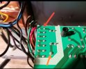
Take out the output tubesI attach pic of the Trace back of the pcb.
The orange arrow points to the black wire that I believe feeds the AC current
To the board, hitting the fuse first.
Then at the other end of the fuse, is the trace going from the fuse to Lug P4 to which the Violet wire is plugged on.

the hooks are the fuse, or a fuse of some type.Hi @Amp Mad Scientist
Ok, will do and let you know.
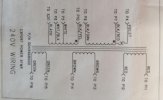
Just occured to me that on the schematics, Blk/Red and Violet wires are shown as in that screenshot.
As already mentioned earlier I had found Blk/Red wire on the P4 Lug and no wire on Lug 7. The Violet wire had been left unplugged.
What is the meaning of the inverted hooks I circled in orange?View attachment 106109


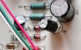
It was a mistake somebody installed it backwards.In this shot you can clearly see that the cap C34 was fitted with its neg pole where the pos pole should have been according o the marking on the PCB.
Why would that have been done that way? View attachment 106110
And here I show the new one I fitted witth the pcb "+" sign marking clearly in sight.
View attachment 106111
Yes, there's power.Take out the output tubes
Set meter for AC volts highest scale
turn power switch on
See the back of the power switch? There is a top pair of terminals with 2 black wires attached.
The bottom 2 terminals attach to wires are brown and blue.
Turn the switch on and measure between those 2 top terminals with the 2 black wires attached.
The rivets on the back of the switch are exposed metal and you can touch your probes to the metal on the 2 terminals
there should be 220V between those 2 rivet terminals.
If there is no voltage there, measure between the 2 bottom terminals with blue and brown wires attached.
There should be 220V between those 2 terminals when the power is on or off.
Do you get voltage at the top 2 terminals when the switch is "on?"