Cutting Circuit boards

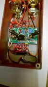
Hi C man, sorry I didn't notice this thread yesterday. Circuit board material is usually fiberglass. Depending on how much needs to be cut I usually either score it a few times with a sharp Stanley knife against a stainless steel rule, then position it on a 90 degree straight edge, hold it down with the stainless steel rule & snap it, then clean the edge up with a file or aluminum oxide stone, even sand paper. An aluminum oxide or carborundum cut off wheel on a dremel works well for not too large cuts but wears down quickly so for larger cuts definitely a diamond cut off wheel. Hopefully the triangular type (round) transistor sockets & zero ohm links are visible in this phone picWP_20170801_001.jpg the links are below the sockets in this GGG Tonebender Mk11 kit. The zero ohm links I can buy over the counter at my local electronics outlet (Jaycar, online only store in US & UK). They are listed as a 0r0, 1/4 watt carbon film resistor, not a link. There must be a reason for using these instead of just a wire link but I haven't looked into yet. When I need transistor sockets (without specifically ordering) I just use the inline IC socket strip & cut off either 3 inline or single sockets & position as I need. I don't have any at the moment to take a pic, but when bought in lengths (20 or more) they have the plastic strip segmented as single sockets so they can be cut off easily. Hope this helps. Cheers
 
Ok, a very quick (single look) google search shows a few reasons for using a zero ohm resistor, none that I think would make a difference in analogue stomp boxes. They can be found in single layer printed circuit boards where the physical layout prevents a continuous copper foil trace (a wire link would suffice). They can be used as a fuse. In circuits containg both analogue & digital components that share a common ground, they are placed between the analogue circuit & ground & the digital circuit & ground to isolate the two circuits. I imagine there are many more uses for as well. Cheers
 
As you say, uses for a zero ohm resistor or a wire jumper. crossing over a track on a single sided board. That's about it really. The only time you would use specifically a zero ohm resistor rather than a piece of wire is in an automatic component insertion machine for large scale production. Fuses need to be actual fuses - the wire is way too thin to survive out in the cold.
 
I am so going to have to digest all that has been said in this thread before I can begin to understand what my electronics mentors are talking about. I have seen quite a number of fellas talk about building their own pedals, but had no clue how one goes about knowing how to design circuits to make distortions, fuzz, delays, compressors, wahs etc. But, if one learns by essentially buying kits and assembling the parts till one accumulates the understanding of the circuit design and components needed to accomplish the "effect" then I can see myself getting to this point one day.
 
That's a good approach, and fuzz is an excellent place to start.

Fundamentally fuzz is just overload - clipping the signal. If you put gain in the signal path, sufficient to turn the guitar signal to - say - 10 volts, but then don't let it get that far, but chop it off when it gets to 1 volt, you've turned your guitar signal into a square wave, which is exactly what fuzz is. The normal way to do the chopping is with diodes, which turn on when the signal gets to about 0.6 volts. A pair of those, one facing each way, will result in a signal chopped off at 1.2 volts.

The more gain you put in front, the wilder will be the fuzz. Put almost no gain in front and you have a simple overdrive.
 
Thanks Bro Don. I actually think I understand what you just explained.

How does one get a board with the proper circuit on it to accomplish this? Are there suppliers who specialize in "generic" Fuzz, distortion etc boards and one just buys and installs such n such diodes, such n such pots, trasnsistor sockets etc?
 
Another thing I can see as an aid to learning are things like this site I just pulled up. With the net, I can see one can also gain quite an understanding of these things by researching info posted in places like these.

I always heard of Electro Harmonix and Bigg Muff's and other types of fuzz's
I guess it is time to dig into what makes things like this tick.

The Big Muff Pi Home Page
 
Thanks Bro Don. I actually think I understand what you just explained.

How does one get a board with the proper circuit on it to accomplish this? Are there suppliers who specialize in "generic" Fuzz, distortion etc boards and one just buys and installs such n such diodes, such n such pots, trasnsistor sockets etc?

Just google for fuzz kits - there's dozens out there. The business of getting it all boxed, pots attached etc is just mechanics.
 
Ah yes, I was kinda hoping Don would give us an answer regarding the zero ohm resistor use. Their use with automated insertion machines makes sense too. Thanks Don.
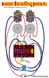
Chilli, fuzzes are an excellent first time pedal project, whether in kit form or scratch built. There are layouts for scratch built (like this)C__Data_Users_DefApps_AppData_INTERNETEXPLORER_Temp_Saved Images_mki_5_tag.png
Tonebender Mk1.5 layout from the turretboard.org site. This one could also be used for a fuzz face by using the suitable values. Germanium transistor sets for various fuzzes are available from Smallbear electronics site & templates for drilling out enclosure's are available in pdf format on sites like General Guitar Gadgets. Sites like diystompboxes or freestompboxes are a great resource for getting a handle on various pedal circuits & how to "tune" germanium fuzzes etc. Pedal building is a rewarding & useful pass time & one I highly recommend. Cheers
 
Back
Top