Hi amp mad scientist,
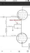
Plate to ground 466.3 vdc
Cathode to ground 33.2 vdc
Actual resistors 320.6 ohms. 2 resistors in series to make 320 ohms. Used for both tubes.
I am using a reasonably new single 8 ohm eminence speaker.
wait did you measure this cathode voltage with amp 4 ohm out connected to 8 ohm speaker?
Should have, because 2 tubes removed.
33.3 vdc
--------- = 0.104 A
320 ohms
.104 A X 466.3 V = 48.5 VA
(volts X amps does not =watts, but that's another subject)
(volts X amps = VA, which is "apparent" power, not true power)
two tubes, 24.25 VA per tube
Now, what is the max watt rating per tube?
What output tubes are you using?
Svetlana EL34= 25 W max per tube
If all the numbers given are correct:
You are running the tubes at 97%..................... not 85%.
However, between 90-100% is correct for class A operation.
However there is a couple errors in this calculation.
We are measuring plate and screen current added together, not plate current alone.
At idle what is the DC voltage drop across the 1K screen resistor?
Or is the screen resistor 1K?
Now you can calculate how much current the screen is drawing, and subtract that from the cathode current, leaving just the plate current - minus screen.