mcblink
Ambassador of Riffs & Spliffs
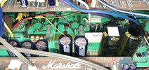
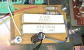
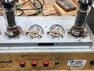
Resize photos. MS Paint is one option, many phones can resize from the options menu, etc. Kindof a pain but the forum's server couldn't handle the large photos anymore so we now have to scale them down a bit.I’m not sure what year it is. It was the screen resistors. I’m trying to send pics but apparently they are too large. Anyone know how to get around this?
Pre 2005ish JCM2k 100w amps are pretty well known for having issues of this nature.
We have a dude here who you'd probably like to talk to about this one, he's helped me through mine and many others as well.
Summoning @Amp Mad Scientist