Yep! Thats one of the cores in the wheel of PIRE( P= Watts, I= Current, R=Resistance, E= Voltage).
Pretty reliable quick reference to figure out each other as long as you have at least 2 values.
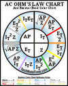
There's another wheel chart thats a lil more advanced but honestly, you wouldnt use it unless you figuring lots of AC power figures . Its name isnt as handy as PIRE: its ZApItEt lol ( z= Impedence, Ap= Apparent Power, It= Current Total, Et= Voltage Total
View attachment 70520
View attachment 70522
Yes, Clockworkmike is onto it, also Don O.
The variations in plate (positive) potential have nothing at all to do with loading down the power supply & is all about the above.
It is why tubes must work into a "load",,,, so that the manipulated current flow is manifested as voltage swings (across the load).
This "load" includes the plate resistor in what we call pre-amp "gain stages" (actually "voltage amplifiers"), the cathode resistor in a cathode follower, the output transformer primary's "reflected" impedance in output transformers. Cheers
Edit:
Actually, I should expand on this (now that I've had my first coffee & onto my second).
During power tube "biasing" (which was the topic that brought this discussion about), the tubes are operating at what we call "quiescent" condition, aka "no signal" condition. At this "idle" condition the tubes are not working across the (reflected) "load impedance" of the OT primary, rather, the DC resistance of that tube's half of the OT primary.
The rising or falling plate potential with bias adjustment is still due to ohms law/current flow through this resistance though.
When an AC signal is applied to the tubes the OT primary's reflected load impedance comes into play. Cheers

.jpeg")