Mystery of the Dead Dr. Z Maz 18 Continued

Amp Mad Scientist

Ambassador of Heresy
Country flag
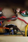
In our last episode we were about to test a 5.6K power resistor.
Can he do it?
Tune in: same Bat Time, Same Bat Channel.

Dr Z Maz 18 power supply.png

What you want to do now is unplug the power.
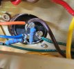
Set meter for ohms.
Find the resistor and measure it.
Two leads on the resistor body.
Black probe on one lead, red probe on the other lead.

The reading is going to move around...
but keep the probes on the resistor until the reading settles down and becomes steady.

If the resistor is good, it's going to read 5.6K or 5600 ohms.

But if the resistor is bad (as suspected), the reading is going to be much more than 5.6K or 5600 ohms.
Now read that resistor and tell us what you are seeing there.

Now as I said before:
don't put the tubes in or try to play the amplifier until you find out what's shorted...
(the resistor is the symptom not the cause)
and all the readings check out correctly.

We are working towards finding the cause....

Do all the tests first,
identify all the problems...
and when everything is correct, put in the tubes last.
Don't try to skip ahead, be patient and take your time with it.
 
Ok.. Sorry.. I can't tell which resistor for sure.. I'll take pic of the guts and maybe you can point it out for me..
 
Oops.. says the file is too large.. I'll send the pic on TGP message
Use microsoft paint "resize" to reduce the size of the file to 2 MB or less.
or use another photo application to shrink the picture down.
I think the limit is 2000 kb.

For all our fans out there, the blue wire leads to the 5.6K resistor.
(red arrow)
We suspect this resistor (where ever it's located?) may be toasted.
Now we got to follow that wire to the resistor.
"C" on the schematic, I believe; in the HT power supply.

maz 18 phase inverter.png

There is voltage at "A"
There is voltage at "B"
But no voltage at "C".

1756374045931.png

Note: keep power UN-plugged.
Don't operate the amplifier.
There is still a short circuit in the amplifier.

Dr Z Maz 18.jpg
 
Last edited:
Best I can tell that blue wire goes to a resistor on the black can (cap I guess) on the chassis.. if this sounds right I can maybe lower it out of the chassis to measure it.. there is a resistor there...
 

Attachments

Best I can tell that blue wire goes to a resistor on the black can (cap I guess) on the chassis.. if this sounds right I can maybe lower it out of the chassis to measure it.. there is a resistor there...
Yes that's the resistor.
If you loosen the clamp you can push up it into the chassis side.
then tighten the clamp back up to hold it in place.
But can you put your ohm meter probes on both sides of the resistor?

I can't see the colors very well.
Should be green blue red if the schematic is correct.
Green = 5 Blue = 6 Red = 00
Try measuring both of those resistors.
Looks like Red-Red-Orange to me
 
Here's the two resistors to the blue wire.. I don't think they are the right colors.. the older non-reverb amp may be a lot different on the schematic.. I think this is a 2007.. pretty old..
 

Attachments

Here's the two resistors to the blue wire.. I don't think they are the right colors.. the older non-reverb amp may be a lot different on the schematic.. I think this is a 2007.. pretty old..
That's OK
unplug power disconnect power
measure the 2 resistors with the ohm meter.
It can be different than the schematic, that's OK.

Take note of the colors.
red = 2, red = 2, orange = 000 = 22K or 22,000 ohms.

Read this for some tutorial.

 
Yep.. those two are good..
What colors are there and what did they read?
Let me know what the result of the test is.

Next test:
Power off, power UNplugged.
Set meter for ohms.
Black probe connect to the metal chassis.
Red probe test the points that I highlighted, wait till the reading stops moving and numbers stand still.
What is the ohm reading at test point #1?
What is the ohm reading at test point #2?

Dr Z Maz Cap1.png
 
I don't why but I'm not getting anything on any ohms scale.. my meter zero's out just fine..
OK.
Let's change the meter to DC volts 1000
you want to tighten the cap clamp up so it holds still.
Black probe connect to chassis
Take out the output tubes
Turn power on
Turn standby on
Test DC volts at test point 1 and 2 with the red probe..
Do you see any voltage at either of the test points? Should be high voltage.
What was the voltage readings?
1756920926585.png
 
Back
Top